4 Digit 7 Segment Display Truth Table
Seven Segment Displays 7 Segment Pinout Types And Applications
Bcd To 7 Segment Decoder Geeksforgeeks

What Is The Truth Table Of A 7 Segment Display Quora
Using Seven Segment Displays Part 1 Nuts Volts Magazine

Pic Interfacing 7 Segment Display Alselectro
Bcd To 7 Segment Led Display Decoder Circuit Diagram And Working
For example the red digits on a digital clock use 2 segment led displays.
4 digit 7 segment display truth table. One pin of all the leds is common. A multiplexed 4 digit seven segment display with only 12 pins seven segment representation of figures can be found in patents as early as 1903 in u s. Notes n is number of 7 segment displays multiplied by 7 each display has 7 inputs. I have only shown the a column.
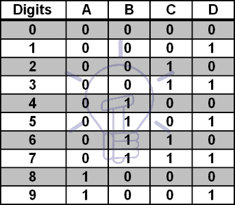
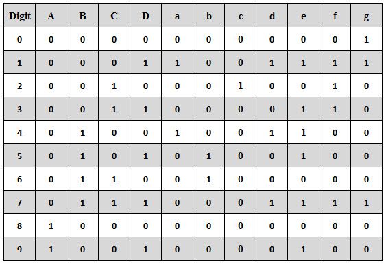
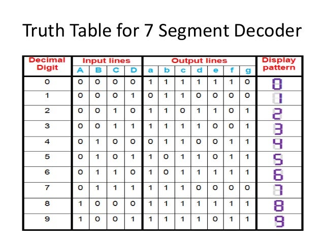
A seven segment display is an arrangement of 7 leds see below that can be used to show any hex number between 0000 and 1111 by illuminating combinations of these leds. In the 7 segment display the simple leds uses to display the decimal character. A truth table of this circuit can be designed by the inputs combinations for every decimal digit. 7 segment displays come in two flavors.
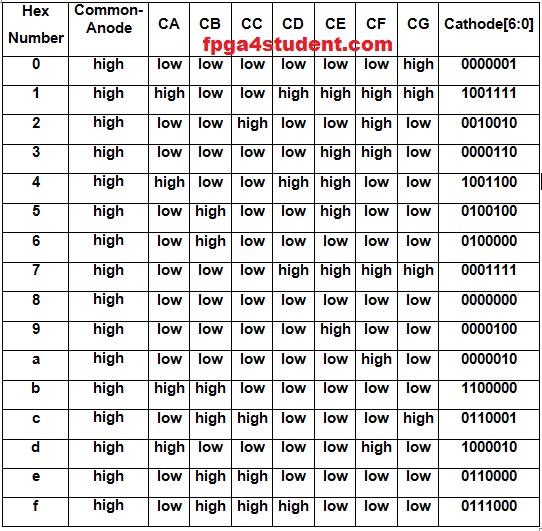
Figure 4 depicts an example timing diagram. The four side input is named as a b c and d. Common anode and common cathode. In the year 1908 f w.
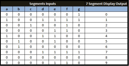
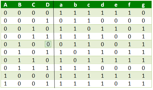
The truth table for the decoder design depends on the type of 7 segment display. The figure below shows the truth table of a bcd to seven segment decoder with common cathode display. The four side input is named as a b c and d. In this example the number of 7 segment displays is configured to 3 as indicated by the generic digits.
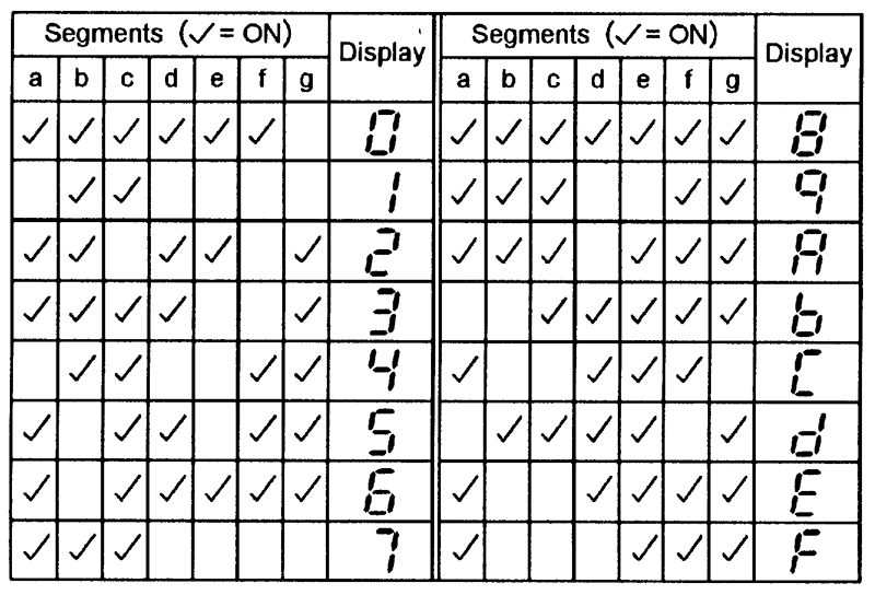
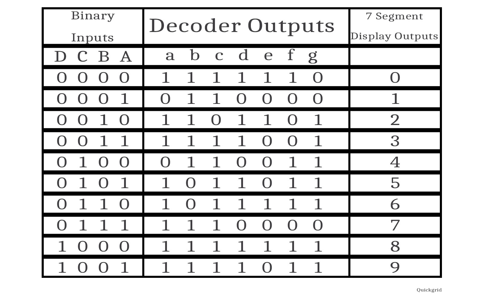
The second step is the truth table design by listing the display input signals 7 equivalent four digit binary numbers as well as decimal number. A 7 segment decoder can show maximum 9 in decimal format it can also show a to f in case of hexadecimal. The decoder takes these four bits and convert them to 7 bits to produce the desired decimal digit to display on the seven segment. The number of 7 segment displays is specified by the digits generic.
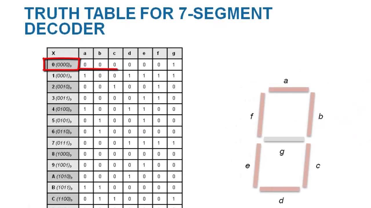
So in order to show 8 9 on display you need 4 bits. Patent 1 126 641 when carl kinsley invented a method of telegraphically transmitting letters and numbers and having them printed on tape in a segmented format. In the device all the leds are placed at a 90 angle from minium two leds. After that in 1910 seven segment display is invented and is illuminated using incandescent bulbs they are used in electric power plants but has gained no much reputation.
Using 3 bits the maximum number we can represent is 7. That pin decides when the anode is common or cathode. The bcd to seven segment display decoder or driver takes 4 inputs and produces 7 outputs. The second step involves constructing the truth table listing the 7 display input signals decimal number and corresponding 4 digit binary numbers.
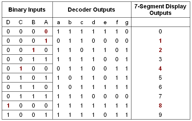
As we mentioned above that for a common cathode seven segment display the output of decoder or segment driver must be active high in order to glow the segment. Internal structure of 7 segment display. The generic bits is set to 10 since it requires 10 bits to. Wood invented eight segment displays which displays the digit 4 by using diagonal bar.

Bcd To 7 Segment Display Decoder Construction Circuit Operation
7 Segment Decoder Implementation Truth Table Logisim Diagram Quickgrid

Interfacing Seven Segment Display With 89c51
Vhdl Code For Seven Segment Display On Basys 3 Fpga Fpga4student Com
Bcd To 7 Segment Display All About Circuits

Bcd To Seven Segment Display Digital Electronics

Arm Cortex M3 Lpc1768 9 Seven Segment Led Interface

Recreating A 7 Segment Display With Adafruit Gfx Ssd1306 Oled T A Tech Blog
7 Segment Decoder

In Depth How Seven Segment Display Works Interface With Arduino

7 Segment Display And Driving A 7 Segment Display
Driving Seven Segment Display With Vhdl Youtube

Mimasv2 7segment Up Down Counter Dream Sdr