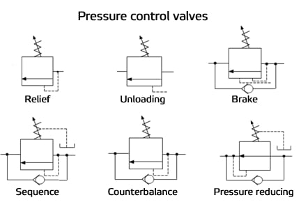
Hydraulic Pressure Control Valve Symbols
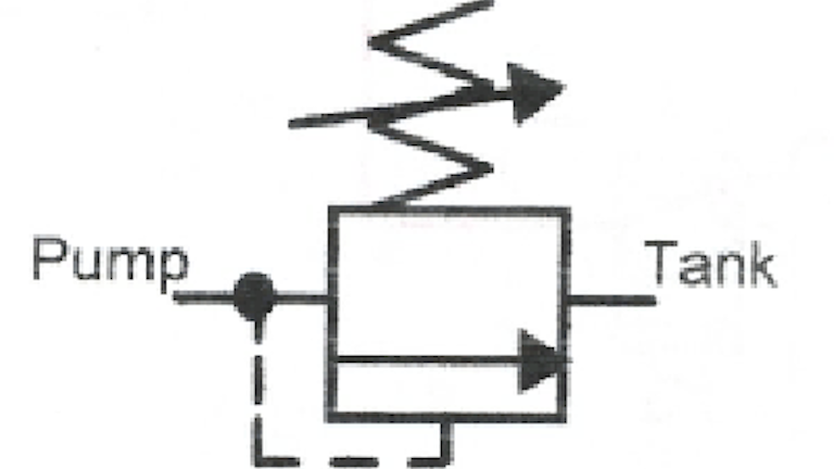
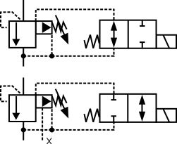
These symbols show 2 way sequence valves with an external pilot and internal drain on the left and external pilot and drain on the right.
Hydraulic pressure control valve symbols. Therefore direction control valves can be designated by number of ports and number of positions and are selected based on the application. Direction of flow hydraulic. Some experience with the directional control valve symbol has already been gained. At this point it is necessary to review the three most common center configurations fig.
Hydraulic circuits can be comprised of an infinite combination of cylinders motors valves pumps and other equipment connected via hydraulic pipes and tubes. Hydraulic offshore supplies basic symbols pressure or return line pilot line two or more functions in one unit flexible hose union cross. Read more about hydraulic symbology in a series from author josh cosford. Hydraulic symbols application information.
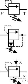
The complexity of these components are difficult to represent fully so a family of graphic symbols have been developed to represent fluid power components and systems on schematic drawings. The symbol on the left shows a sequence valve with a manually adjustable set point and the one on the right has an externally controlled pilot switching pressure and internal drain. Pressure control valves are typically pilot operatedpilot operated ñ that is the valve is moved automatically by hydraulic pressure and not by a person. Any exceptions are noted.
The valves used for accomplishing the above mentioned system functions are therefore given the following names. Heat exchangers filters lubricators and dryers hydraulic pumps relief and unloading valves continued directional control valves continued. The directional control valve symbol is the most intuitive and selfexplanatory of the symbols. It controls the actuator s position and direction by controlling the fluid flow into the actuator.
As the phrase fluid power implies these symbols cover both hydraulic and pneumatic components. Bypassed from points of high pressure to points of low pressure. The basic valve symbol is a square which represents thebypassed from points of high pressure to points of low pressure valve body or spoolspool. Direction of flow pneumatic.
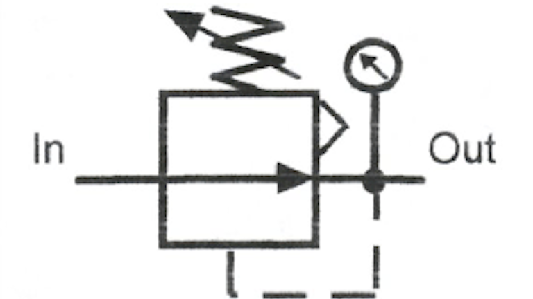
A direction control valve is a vital component in a hydraulic system. Control valve series directional control valve with negative overlap and valves in spool. 3 1 for spool type directional control valves. Fluid power symbols 10 13 3 pressure reducing 10 13 4 pressure reducing and relieving 10 13 5 airline pressure regulator adjustable relieving 10 14 infinite positioning three way valves 10 15 infinite positioning four way valves 10 16 flow control valves see 3 7 10 16 1 adjustable non compensated flow control in each direction 10 16 2 adjustable with bypass 10 16 3 adjustable and pressure compensated with bypass 10 16 4 adjustable temperature and pressure compensated.

